If you’ve ever stood in front of a working Motor Control Center (MCC) during a plant’s startup or routine maintenance, you’ve likely noticed that it’s more than just a row of switchgear and contactors. It’s a coordinated system where every component works in sync to keep motors running reliably—and one of the most powerful, yet underdiscussed, parts of that coordination is cascade control. As an MCC supplier with over a decade of designing, building, and retrofitting these systems for manufacturing, water treatment, and food processing facilities across North America, I’ve seen firsthand how a well-implemented cascade control system turns erratic motor performance into consistent, energy-efficient operation. Today, I want to break down how it works, why it matters, and how our team tailors these setups to solve real-world pain points for our customers. Motor Control Center
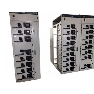
First, let’s ground this in what a basic MCC does, because cascade control doesn’t exist in a vacuum. An MCC is a central assembly of electrical components—circuit breakers, motor starters, overload relays, and control logic—that distribute power to individual motors and manage their operation. Every motor in an MCC is assigned a specific task: driving a pump that circulates process water, powering a conveyor that moves raw materials, or spinning a fan that cools a production line. For most of these tasks, motor performance isn’t “good enough” if it’s inconsistent. If a pump’s speed fluctuates, it can damage pipework, waste energy, or cause a process to shut down unexpectedly. That’s where basic control systems fall short: they use a single sensor to adjust motor output, which often reacts too slowly or overcorrects, leading to instability. Cascade control fixes that by adding a secondary layer of logic, turning a reactive system into a proactive one.
Let’s use a common, relatable example to make this concrete: a municipal water treatment plant’s raw water pump station. This is the setup we design for many mid-sized municipalities, and it’s where cascade control shines. The primary goal here is to maintain a steady water level in the plant’s raw water holding tank. If the level drops too low, the pump needs to speed up to refill the tank; if it rises too high, the pump slows down or stops. A basic single-loop control system would use just one level sensor at the tank to send signals to the motor in the MCC. If the level drops, the sensor tells the MCC to increase the motor’s speed. But here’s the problem: that pump is pushing water through hundreds of feet of pipe, so the signal from the tank doesn’t reach the motor instantaneously. By the time the motor speeds up, the tank level has already dropped further than intended. Worse, if the overcorrection swings the level too high, the motor might slow so much that the level spikes in the opposite direction. This back-and-forth—called “control loop oscillation”—wastes energy, wears out the motor’s contactor faster, and can even cause the tank to overflow or run dry.
A cascade control system solves this by adding a second sensor and a secondary control loop, nested inside the primary loop. Instead of just monitoring the tank level, we add a pressure sensor near the pump itself, right at the MCC’s motor starter. That secondary sensor tracks the actual flow rate of water being pumped, which is a direct, immediate measurement of how hard the motor is working at any given moment. Here’s how the sequence plays out step by step, and this is the logic we program into the MCC’s integrated programmable logic controller (PLC) every time:
- The primary loop (the “master loop”) is assigned to the tank level sensor. Its job is to define the setpoint—the desired tank level, say 10 feet. If the tank level drops to 9.5 feet, the master loop sends a signal not directly to the motor, but to the secondary loop (the “slave loop”) inside the MCC. This signal is a target: “adjust the pump to achieve a flow rate of X gallons per minute to get us back to 10 feet.”
- The secondary loop (the “slave loop”) uses the pressure/flow sensor at the pump’s MCC starter to monitor real-time performance. The slave loop’s job isn’t to maintain the tank level—it’s to hit that target flow rate as fast and as smoothly as possible. If the pump’s current flow is too low, the slave loop tells the MCC’s variable frequency drive (VFD) attached to the motor to speed up just enough to reach the target. If the flow is too high, it slows the motor down, not by a random amount, but precisely to match the demand from the master loop.
- The two loops communicate constantly, updating every 50 milliseconds (a standard we use for critical applications) rather than every few seconds like basic single-loop systems. The master loop only adjusts its target if the tank level changes—so if the plant’s water treatment process ramps up and needs more water, the master loop sends a new target to the slave loop, and the MCC adjusts the motor’s speed without any lag.
This nested structure is what makes cascade control so effective. The master loop handles the overall, long-term goal (maintaining tank level), while the slave loop handles the fast, dynamic adjustment (motor speed/flow). We see this same logic applied to almost every motor-driven process an MCC supports: conveyor speed for packaging lines, fan speed for HVAC systems, even mixing motor speed for chemical processing where consistency is non-negotiable.
Now, I want to be clear: cascade control isn’t a “one-size-fits-all” add-on. That’s a mistake some less experienced integrators make, trying to jam it into every MCC regardless of the application. As an MCC supplier, we start every project with a deep dive into our customer’s process needs, not just a parts list. For example, a food processing plant that uses a motor to move dough through a sheeter has different requirements than a water treatment pump. The dough sheeter’s motor needs to maintain a precise, steady speed to avoid uneven dough thickness, which would ruin batches. A single-loop system would struggle if the dough’s consistency changes—if it’s softer one day, the motor would speed up, leading to lopsided sheets. A cascade control system here would use a primary sensor measuring dough thickness after the sheeter (the master loop) and a secondary sensor measuring motor torque at the MCC’s starter (the slave loop). The master loop adjusts the speed target based on dough thickness, and the slave loop adjusts torque to match, so the motor never overworks or underworks even if the raw material changes.
Another critical point: cascade control improves not just process stability, but motor and equipment lifespan—and that’s a big win for our customers’ bottom lines. Every time a single-loop system overcorrects, the motor’s contactor, VFD, and even the pump or fan have to work harder to compensate for lag. We’ve seen customers go from replacing a pump every 18 months to every 7 years after we retrofitted their existing MCC with a cascade control system. Energy costs drop too, because the motor isn’t wasting power on unnecessary speed adjustments. For a mid-sized manufacturing plant, that can add up to $20,000 to $50,000 a year in savings—numbers we don’t just pull out of thin air, but track on every project we complete.
A common question we get is: “Do I need a fancy new MCC to add cascade control?” The answer is no, but there are important caveats. If your MCC already has a PLC and VFDs (most modern MCCs do), we can program the cascade logic into the existing controller—no need to replace the entire unit. For older MCCs that use hardwired relays instead of a PLC, we can add a compact PLC module to the MCC’s control compartment and rewire the sensor inputs to create the slave loop. We always prioritize retrofits first because they’re more cost-effective, but for new builds, we integrate cascade control from the design phase, which lets us space sensors optimally and program the loops to match the exact process flow.
I want to share a recent example that drives this home. Last year, we worked with a regional grain elevator that was dealing with consistent downtime on their grain conveyor system. The single-loop control in their old MCC would cause the conveyor to surge every time the grain hopper fed more material, leading to frequent belt slippage and motor overload trips. The elevator’s maintenance team was spending 10+ hours a week fixing trips and replacing worn belts. We designed a new MCC with a cascade control system for their two main conveyors: a primary level sensor at the hopper (master loop) and a secondary speed/torque sensor on each conveyor motor’s VFD (slave loop). Within two weeks of installation, their downtime dropped by 90%, and their maintenance costs for the conveyors fell by over $12,000 in the first six months. That’s the impact cascade control can have when it’s tailored to the customer’s specific pain points.
Let’s also address a few misconceptions about cascade control that we hear all the time. Some operators think it’s too complex for their team to maintain, but in our experience, once we do a 2-hour training session on how the system works and how to check the sensor readings through the MCC’s HMI (human-machine interface), most teams find it simpler than basic systems because they don’t have to deal with constant adjustments. Others worry about sensor failure, but we build in redundancy for critical applications: dual sensors for both master and slave loops, so if one fails, the system switches to the other without shutting down. That’s a non-negotiable for facilities where downtime means lost production or regulatory issues, like water treatment or pharmaceutical manufacturing.
At the end of the day, a Motor Control Center is only as good as the logic that controls its motors. Cascade control isn’t just a technical upgrade—it’s a way to turn a standard MCC into a system that adapts to your process, reduces waste, and extends equipment life. We’ve built hundreds of MCCs with cascade control for customers across industries, and every time, the feedback is the same: “We didn’t realize how much our processes were suffering from lag until we installed this.”

If you’re dealing with inconsistent motor performance, unexpected downtime, or rising energy costs tied to your MCC operations, our team can help. We don’t just sell you an MCC—we work with you to assess your process, design the right control logic (including cascade control where it makes sense), and provide ongoing support to make sure your motors run smoothly for years. There’s no one-size-fits-all solution, but there is a solution that fits your specific needs, and we’re here to help you find it.
Cable Branch Box References
- Bolton, W. (2015). Instrumentation and Control Systems. Newnes.
- Li, Y., & Yang, Q. (2020). Advanced Control of Motor Drives for Industrial Applications. IEEE Press.
- Motor Control Center Design and Application Guide. (2022). National Electrical Manufacturers Association (NEMA).
- Ogata, K. (2010). Modern Control Engineering. Pearson.
Jiangxi Yihong Electric Power Technology Co., Ltd.
Address: Chating Industrial Park, Guangxin District, Shangrao City, Jiangxi Province
E-mail: 15779933057@163.com
WebSite: https://www.yihcn.com/
